
TL;DR: Jesse extended his trip to Shenzhen by a week. We’ve solved many of the issues mentioned in the last update. The first samples made by the factory weren’t quite right. Second samples should be done in the next week.
Hello from Shenzhen and Oakland,
Things are proceeding apace, though it hasn’t all been sunshine and puppy dogs.
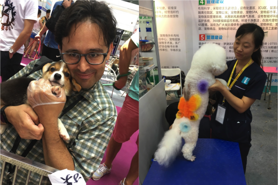
(Disclosure, it’s been sunny and in the high 90s most days since Jesse arrived in Shenzhen. And he did take a Saturday morning off to attend a pet expo featuring a puppy bearing a charming facsimile of our logo.)
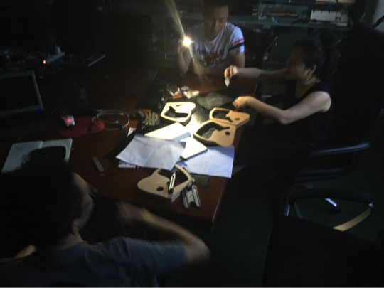
The design process took some time. Jesse’s been working directly with the factory’s mechanical engineer, electrical engineer, head of R&D and our amazing sales person, Maggie. Most days at the factory start around 9:30 and wrap up somewhere between 8pm and 10pm. For the past two weeks, we’ve all been gathered in a conference room, working through design and assembling prototypes. One afternoon, the power went out, which meant no AC and, eventually, no light. So we ended up designing by mobile phone light.
Mechanical
On the mechanical front, we’ve made amazing progress over the past few weeks.
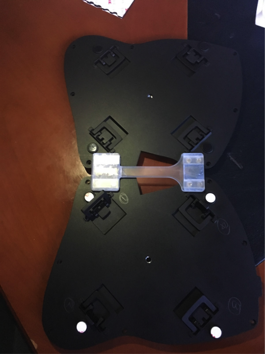
We’ve got feet that work. We’ve got an incredibly simple interconnect mechanism that, working with the feet, will let you tilt and tent your Model 01 at the same time. We’ve got a ¼-20 tripod mount on the bottom of each half of the keyboard, so that you can do crazy things with your Model 01’s placement and angle if you want to.
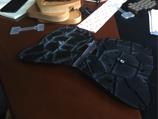
Prototype of the interior base plate with tripod mounts
Getting to the first samples from the factory took a bit more time than expected.
First, we went through a couple interconnect mechanism proposals. Nothing was really working all that right, so we stepped back and looked at the sliding dovetail mechanism Jesse and Brian Garvey designed for the Highway 1 Demo Day prototype. We were in love with the design, but a mechanical engineer we were working with talked us out of it, since he said it’d be way too expensive to make.
Prototype of the interior base plate with tripod mounts
Flash forward to the point where we’re working with a factory, who can actually tell us what it costs to make various solutions. The sliding dovetail turns out to be pretty workable.
We got first samples of the new enclosure and sliding dovetails back late last week. (They were actually supposed to be back last Monday, but the factory’s prototype supplier completely blew their deadline. And their second deadline. And their third deadline. And then the parts they got back to us had a bunch of machining errors. Thankfully, we were able to use the bad parts to learn a lot about the updated design, including numerous things that worked great and a few things that just weren’t right.)
For the previous prototype, we had a single bar you could flip over if you wanted to switch the keyboard from a flat configuration to a tented configuration. That only worked because the feet we were using at the time were bolted onto the bottom of the keyboard. We, of course, still plan to let you tilt and tent your Model 01. With the new design, the feet are actually built into the bottom plate, so the flat center bar needs to be a lot thinner.
The plan is to ship with a thin, flat center bar and a tented center bar with stabilizing feet built in for when you’re using your keyboard tented and tilted on a desk.
The feet we designed were a collaboration between Jesse and the factory’s mechanical engineer. They’re absurdly simple. But they get us tilted and tented configurations when the keyboard is connected together or when the two halves are separated.
For a while, we thought we were going to need to do something clever and complex, like our friends at UGL did for the Ultimate Hacking Keyboard. They designed screw-on feet that users can rotate to get the different angles they needed. We looked at feet that locked at multiple angles. We looked at feet that had screw-out extensions. We actually made screw-on feet that locked at multiple angles and had screw-out extensions. They were expensive. They were complicated. They were a pain to set up. What they weren’t was particularly sturdy.
What we ended up with is flip-out plastic feet, similar to what you’d see on most keyboards, but with a few key differences. Rather than being placed parallel to the front and back of the keyboard, they’re placed at a 45 degree angle. Also, the bottoms of the feet aren’t flat. They’re cut with three different angles on them. Inside each foot is a mini-foot. With these feet, you can tilt your keyboard forwards or backwards. You can tent your keyboard so the middle is higher than the outside and and you can tilt and tent your keyboard at the same time. You can also reverse-tent your keyboard, so the middle is lower than the sides. But don’t do that. It’s bad for your hands.

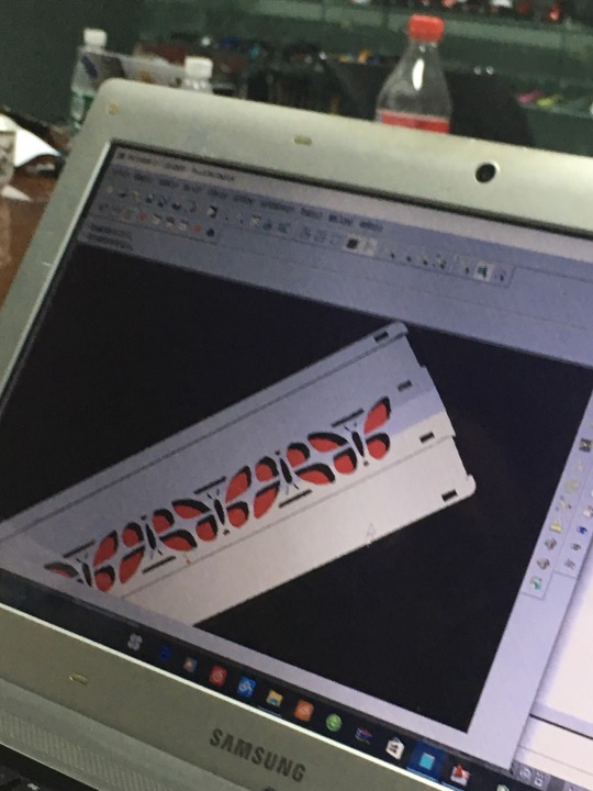
CAD Model of a foot
A 3D-printed foot prototype
The last time Jesse was in Shenzhen, he met with two wood suppliers. One was the supplier found by our ex-factory. The other was a new supplier he met through one of our candidate factories. In June, we got samples from that second supplier. They were really, really not very good. The supplier apologized and offered to make new samples. We visited them the week before last to pick up the updated samples and to discuss how the project might move forward if we picked them. One of the new, supposedly perfect, samples had a crack that had been glued back together. To say we were disappointed or frustrated would be something of an understatement.
We also got updated wood samples back from our preferred wood supplier, with whom our factory is now working directly. They look and feel fantastic. :)
Yesterday, we went through a comprehensive mechanical design review, so that the factory could place an order for new mechanical prototypes today. We’re expecting the new samples by this weekend.
Keycaps
The keycaps have seen only minor changes. The Escape and Butterfly keys got slightly reworked to have a cleaner interior corner. The thumb keys got slightly tweaked so that they won’t get caught against each other when pressed down. Also, all the keys all finally got numbers embossed on the insides. Initially, the plan was for the keys to get the same “row and column” numbers we use on the PCBs and in the firmware. The factory’s team protested that they usually do things differently, just giving each key a number. We said that that was very nice, but that our way would be easier for users to figure out without a diagram. A couple days later, we finally came to understand that the numbering system the factory proposed was actually about making assembly easier and more reliable for the staff on the production line. Once we understood that, the decision was an easy one. The keys will be numbered from 1 to 64, so they’re easy for the factory’s assembly line staff to assemble. We’ll provide you with a nice diagram showing where each key goes.
As of now, the only thing left on the keycaps is to verify that once they’re painted and UV coated, everything still fits well. The test keycaps got painted on Monday and we should see them tomorrow.
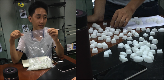
Sorting unlabeled keycaps makes one sad
It sounds like our minimum order quantity for alternate key legends (like Dvorak, Colemak, Bepo, Nordic, etc) is about 500 sets. We’re still waiting on the costs, but at a guess, we’ll be able to do alternate labels if we have 100-125 preorders for extra keysets of a given layout. The nice thing is that production of those keysets is something we can spin up pretty quickly once the initial injection molds are made. In the not too distant future, we’ll run a survey to gauge interest in the likely alternate layouts.
Electrical
When last we wrote, the big blocker on the electrical front was availability of the ATMega32U4 chip the Model 01 depends on. We jumped through a bunch of hoops with two potential resellers and even reached out directly to Microchip, who now own Atmel. Things were looking complicated, expensive and slow. We started asking everybody we met if they had a secret source for the ATmega chips we needed. We debated just swallowing a couple thousand dollars in extra costs, buying them from DigiKey in the US and FedExing them to Shenzhen. And then we asked our friends at Arduboy, who make a really neat pocketable game console based around the ATMega32U4. As it turns out, the supplier they’re getting their chips from can’t really help us, but one of their other suppliers happens to have a whole passel of the chips we need sitting in their warehouse in Shenzhen. So we bought them. Yay!
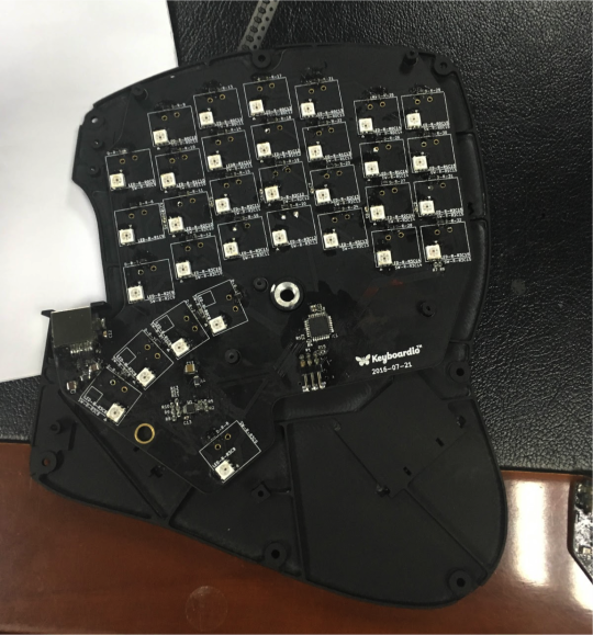
Over the past week, we’ve been working with the factory’s electrical engineer to triage why the sample PCBs they made for us just weren’t working right.
As we’ve worked together, the sample boards have gone from “Wha???” to mostly, sorta, kinda working and then to “seem pretty ok”
“Seem pretty ok” isn’t really quite good enough. We think we know what went wrong and we’ll be pushing hard on the electrical front this week.
Some of the problems came down to issues with hand-soldering tiny components. Careful testing and rework have solved these issues. This won’t be an issue in production. All of the boards will be assembled by machine.
Some of the problems may be related to parts substitution, which can be a really serious issue when getting electronics made. The way it’s supposed to work is that a product designer will specify which components of an electrical design will be ‘consigned’ to the factory by the customer, which components will only be purchased from an 'assigned’ manufacturer or distributor, and which parts are 'generic’ and can be purchased from whomever the manufacturer wants. In our case, there are no consigned components, but a number of assigned components. We’re particularly picky about the Atmel microcontrollers and the APA LEDs, but we also care deeply about the RJ45 jacks (specified as coming from TE), the USB Type C jack (from JAE), and a bunch of other, more minor stuff.
The factory agrees 100% with us that under no circumstances should they be substituting any parts without our express authorization. But, when building the prototype boards, that’s just what happened. The two places it was most visible were in the USB Type C jack, which didn’t latch very well and in the RJ45 jack, which had a slightly different PCB footprint than the one we’d specified. As we dug into the issue, what happened was that some of the suppliers weren’t able to get samples of the parts we needed on short notice and just substituted parts they thought would be a good match. That’s not going to happen again.
As the factory researched what had happened, a couple of their suppliers expressed frustration that we had specced expensive foreign parts, when there are solid locally made alternatives that they believe will work just as well. The factory’s proposal is that for the next test build, they’ll make two versions of each board. One with local versions of parts and one with the versions we’d originally specified. We’ll get a copy of the proposed alternative BOM and part numbers and datasheets for everything substituted and then we can make an informed choice about BOM changes. They’ve already set us up with new options for the RJ45 and Type C jacks that are totally reasonable. As we make our choices on component substitution, we’ll be focusing on quality, availability and support, more than on price.
(A brief note on the USB Type C jack: we’re shipping with a USB A to C cable. So the bit that plugs into the keyboard is the small and reversible Type C, but the other end will fit into the Type A USB port that’s already on your laptop, desktop, or USB hub.)
By far, the biggest problems were, we think, related to a miscommunication around assembly instructions. When we designed the two PCBs for the two halves of the Model 01, we designed them as separate boards, rather than one board with two halves. As such, we repeated certain part identifiers between the two boards. For example, both boards had a resistor numbered “R14”. On the left hand, R14 is a 10k Ohm resistor. On the right hand, R14 is a 500k Ohm resistor. Raise your hand if you can see where this is going. So yeah, the EE didn’t work from the schematics or parts placement files when assembling the boards. Instead, he worked from the combined BOM we’d sent along with the bid packet for pricing. This was the result of a misunderstanding, the language barrier, and a bad design choice on our part. The misunderstanding has been corrected and the part numbers on the right hand board have all been updated.
The last ‘big’ problem, once we got the components on all the boards sorted out, was that the tool we use to flash the firmware onto the ATTiny chips that drive the keyscanning engine doesn’t work quite like Jesse thinks it does. We spent two days chasing our tails because the boards worked erratically. The factory brought in a partner company to help triage the boards. While they were working on one set of boards, Jesse went across town to do some debugging with Charles Pax, an American hardware hacker living in Shenzhen. Charles makes a nifty temperature sensor and data logger called the Pax Instruments T400. (Yes, that is a plug for his product. He didn’t ask for it. But he deserves it, because he’s a hero.)
Charles happens to have a very reasonable EE bench and rework station at his apartment in Shenzhen. Working with Jesse, he traced the issue down to a difference in the behavior of the ATTiny chips on the boards we brought from the US and the ATTiny chips on the local boards. Charles swapped the chip on a ‘good’ board and a ‘bad’ board and magically the bad board started to work. From there, a little bit of investigation pointed the finger at the ‘fuses’ on the bad ATTiny. The fuses are, essentially, how you configure the chip. And you need to actually set them correctly or your chip will work erratically or not at all.
Now that we know what went wrong, the most astonishing thing about the first sample circuit boards is that they work at all. Seriously. It’s kind of nuts.
Over the weekend, the factory did a test of automated assembly of the PCBs. Aside from some issues with overcooking the LEDs the first time through the solder reflow oven, the new boards work much, much better.
What’s next
Jesse’s headed home to Oakland tomorrow night. Right now, it’s looking like he won’t be heading home with a fully integrated sample unit of the Model 01. We’re expecting it in about a week by FedEx or DHL. Once we have the sample, we’ll be able to formally sign off on the design and the factory will start work on injection mold tooling.
The Schedule
The delays on getting the prototype’s mechanical parts built has put us 1-2 weeks behind the factory’s most ambitious estimated schedule. (That is, 1-2 weeks past October 19.) They owe us an updated schedule and we expect it later this week, but didn’t want to hold the backer update for it.
<3 j + k